Categories

Newsletter

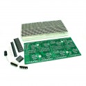
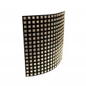
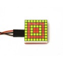
16x24 Red LED Matrix Panel - Chainable HT1632C Driver

3.3V and 5V LED Matrix Module with 16x24 pixels and HT1632C driver measuring 75.6mmx113.5mm.

More details

Availability: SHIPS TODAY

Last Updated: 03/28/2024

Tinkersphere

TS2197

$24.49

Features:

  • 16x24 pixel LED Matrix
  • Color: Red
  • Operating Voltage: 2.4V - 5.5V DC
  • Number of Pixels: 384
  • Driver: HT1632C
  • 3-pin Serial protocol (similar to SPI)
  • Adjustable display brightness
  • Can be set to flash at 1Hz
  • Cascadable design
  • Fully assembled
  • Control via 3 digital output pins on your microcontroller
  • Arduino and Raspberry Pi compatible
  • Dimensions: 75.6mm x 113.5mm
  • Operating Temperature: 0 - 45C
  • Power Consumption: <1.8W
  • Static display which does not need real-time scanning
  • Supports both parallel and series cascading for seamless connections in any direction
  • Pixel Size: 3.75mm
  • Pinout:
    • VCC: Power Input (2.4V - 5.5V DC)
    • GND: Ground 0V
    • DAT: Serial Data Input
    • #WR: WR Write Clock Input (Data on the DATA lines are latched into the HT1632C on the rising edge of the WR signal)
    • #RD: RD Read Clock Input (The HT1632C RAM data is clocked out on the falling edge of the RD signal. The clocked out data will appear on the DATA line. The host controller can use the next rising edge to latch the clocked out data.)
    • #SC: SC Select Chip (When the SC line is high, the data and command read from or written to the HT1632C is disabled, and the serial interface circuit is also reset. If SC is low, the data and command transmission between the host controller and the HT1632C are all enabled.
    • OSC: If the RC Master Mode command is programmed, the system clock source is from on-chip RC oscillator and system clock is output to OSC pin. If the Slave Mode or EXT CLK Master Mode command is programmed, the system clock source is input from external clock via the OSC pin.
    • SYN: If the RC Master Mode or EXT CLK Master Mode command is programmed, the synchronous signal is output to SYN pin. If the Slave Mode command is programmed, the synchronous signal is input from SYN pin. 


Connection for Raspberry Pi:

RPI LabelPinSURE LabelPin
GND6GND8
5V45V16
GPIO 10 (MOSI)19DAT7
GPIO 11 (SCLK)23WR5
GPIO 8 (CE0)24OSC2
GPIO 7 (CE1)26SC1


Connection to Arduino:

  • VCC to +5V
  • GROUND to Ground
  • DAT to D2
  • WR to D3
  • SC to D4
Any details on how to use this with a Raspberry pi?
I used this library https://github.com/mchestr/HT1632C-Python Happy tinkering!
Default User Icon Ryan · 07/31/2021
Was this answer helpful? (0) (0)
Hi, I checked the github posted and wonder how the user can feed texts to Raspberry Pi and then, the LED matrix?
You can scroll a message on the LED matrix by replacing "Hello World!" with your desired text in the file https://github.com/mchestr/HT1632C-Python/blob/master/examples/message.py and loading it to the Raspberry Pi
Default User Icon Sara · 07/24/2023
Was this answer helpful? (0) (0)
Is there a maximum of units that could be chained? and how to provide the power supply to the chain. Thanks!
Yes, up to 8 can be chained. The power supply should be 5 volts with a max amp power rating above or at the sum current usage of all the chained boards together.
Default User Icon Sara · 07/24/2023
Was this answer helpful? (0) (0)
is it able to display motion graphics? for example, the moving texts
Yes, you can make a scrolling display with these.
Default User Icon Sara · 07/24/2023
Was this answer helpful? (0) (0)
How long could it be chained
Up to 8 boards can be chained.
Default User Icon Sara · 07/25/2023
Was this answer helpful? (0) (0)

Customers who bought this item also bought